GENIE BFG
What is the Bespoke Framework Generator (BFG)?
Ian Henderson (I.R.Henderson@reading.ac.uk)
This page provides an introduction to BFG, as I understand it -- it is essentially a write-up of notes made during my visit to Manchester in August 2006. Please correct any mistakes you find, or let me know of any problems. Information about BFG direct from its creators can be found on the University of Manchester's BFG webpages.
Introduction
Climate model frameworks are often constructed using bespoke code tied to specific technologies. Such frameworks tend to be inflexible: it is difficult to add new models or swap existing ones, change the way the framework runs (e.g. from a sequential to concurrent mode, or vice versa), and programming effort is duplicated many times over as each framework uses its own implementation of common functionality. The University of Manchester Centre for Novel Computing is therefore developing a framework generator that climate scientists can use to produce customised ("bespoke") frameworks: this tool is called the Bespoke Framework Generator (BFG). The user supplies BFG with metadata about the models in the framework (their interfaces for initialisation and coupling), how they communicate (where coupling data comes from and goes to), and how the framework is to be deployed (e.g. the number of executables and MPI processes, and the order in which models should run). The user then runs BFG, which automatically generates appropriate framework source code from the supplied metadata. Where models are coupled using point-to-point communications embedded in the source code (e.g. MPI_Recv, MPI_Send, prism_put, prism_get), the user will need to substitute the function calls with calls to BFG "put" and "get" function calls, and specify the desired communications technology in the BFG metadata. BFG then creates appropriate "put" and "get" implementations that wrap the particular coupling technology requested by the user. (Framework metadata is currently supplied to BFG through a series of XML files that must be edited manually; it is possible that these BFG input files may be generated automatically from a GUI in future, which will guide the user seemlessly through the framework definition and generation process.)
Control code and "minimal compliance"
BFG will usually create the control code (timestepping code) for a model framework itself. However, BFG can still be used with models that contain their own control code. This may be desirable in cases where an existing model's control code is difficult to isolate. Models that only make use of BFG "put" and "get" and do not allow BFG to create control code are referred to in BFG terminology as having "minimal compliance". Such models must have one entry point subroutine that BFG can call to start the model, but apart from that all control is handled within the source code for the model itself: initialisation, timestepping and deinitialisation are carried out internally. The PRISM coupler, OASIS, is designed to work this way - it does not generate control code, instead relying on the individual models to control themselves.
BFG 2 developments
Coupling through argument passing
BFG can be used to create flexible and extensible frameworks for existing sets of models, or to create such frameworks for new sets of models - an example of the former is GENIE; the latter, FLUME. Work with both these sets of ESMs is helping to drive current BFG development. The first version of BFG, BFG1, worked with toy models and only used point-to-point communication (put and get) for coupling. Coupling through argument passing (as used in the native GENIE framework implementation) was possible, but inefficient and obtuse. Table 1 below compares BFG1 and BFG2 methods for coupling sequential argument-passing models:
| Argument passing simulated using point-to-point communications in BFG1; "field" is stored three times: in Atmos(), Ocean(), and in put() where it is buffered for subsequent get()s. | Argument passing in BFG2; "field" is only stored once - in the main UpdateFramework subroutine, where it is passed by reference to Atmos() and Ocean(). |
subroutine Atmos()
  real :: field
  ...
  put( field )
end subroutine

subroutine Ocean()
  real :: field
  get( field )
  ...
end subroutine
subroutine UpdateFramework()
...
do timeStep = 1, N
call Atmos()
call Ocean()
end do
...
end subroutine
|
subroutine Atmos( field )
  real, intent(OUT) :: field
  ...
end subroutine

subroutine Ocean( field )
  real, intent(IN) :: field
  ...
end subroutine
subroutine UpdateFramework()
real :: field
...
do timeStep = 1, N
call Atmos( field )
call Ocean( field )
end do
...
end subroutine
|
Argument passing simulated with BFG1 is undesirable because coupling fields are stored three times in memory unnecessarily.
Coupling with PRISM
Another development in BFG2 is the use of the PRISM coupler, OASIS (version 4). BFG2 will effectively wrap the OASIS functionality - BFG put and get will wrap prism_put() and prism_get(), and BFG will generate initialisation subroutines for each coupled model containing appropriate PRISM initialisation code that defines coupling fields ("transients" in PRISM terminology) and the grids over which those fields are exchanged by the OASIS coupler - prism_def_var(), prism_def_grid(), etc.. (To do this, appropriate metadata descriptions of model grids will be required - a "gridspec".) Note that BFG2 is designed to be coupler-independent - it will be possible to create frameworks that use different coupling methods in future just by specifying appropriate metadata.
BFG methodology
BFG methodology is summarised by the terms "Define", "Compose" and "Deploy" (DCD). These terms correspond to three metadata (XML) files containing definition, composition and deployment information for a model framework.
Definition
BFG definition data is associated with each model within a framework. The definition data describes the interface to the model. The interface may either consist of entry point subroutines and their arguments (an argument-passing, or "argpass" interface), or put and get calls embedded in the model source code (an "inplace" interface), or a mixture of the two. Entry point subroutines comprise:
- Initialisation subroutines, called at the beginning of a run to initialise the model;
- Iteration subroutines, called periodically at specified timesteps during a run to update the model;
- Finalise subroutines, called at the end of a run to deinitialise the model.
There may be more than one initialisation, iteration or finalise entry point associated with a particular model; where necessary, the order in which entry points are called can be specified using "constraint" data (e.g. "init1" precedes "init2"). Arguments to entry point subroutines are described by direction (in/out), datatype, dimension, and an ID corresponding to the position of the argument in the argument list. The argument definition does not include a name for the argument, just the positional ID. Entry points can also have "inplace" fields associated with them - puts and gets carried out by or under the entry point function.
Definition data is fixed for a given model, and doesn't change unless the model changes. Changes to composition and deployment data can be made without changing model definition data.
N.B. GENIE models and FLUME Met. Office models communicate by argument passing (rather than put and get). The need to create frameworks for models that use an argument-passing interface was one of the main drivers behind BFG2 (only inplace put and get style point-to-point communication was supported in BFG1). Put and get may still be used for diagnostic output in GENIE and FLUME though - it is considered easier to output diagnostics at the point in a model's code where they're calculated, rather than pass them up the call stack to an entry point function. This allows the separation of prognostic fields (arg passing), and diagnostic fields (in place output) in GENIE and FLUME. It is also possible to mix inplace and argpass field exchange: a field passed out of one model via an entry point function may be read in to another model via an inplace "get", for example.
Composition
BFG composition data describes how fields are connected between models. This is done in two different ways for "argpass" and "inplace" I/O.
"Inplace" I/O
For inplace I/O (BFG "put" and "get"), output fields (puts) in models are connected with corresponding input fields (gets) in other models using "point-to-point notation": the IDs of input and output fields are matched up in the composition metadata. The notation used is uni-directional, and sometimes referred to as a "channel". (A similar method is used in the SMIOC metadata used in PRISM coupling.)
"Argpass" I/O
For argpass I/O (passing of fields through timestepping subroutines), set notation is used in the composition data to describe how arguments are connected across different models. Since the order entry point subroutines are called in affects how fields are connected across models, it was considered simpler to use set notation (rather than point-to-point) for argpass I/O - connections between fields are made by grouping together the subroutines that use a particular field, with no reference to where the arguments come from, as this is determined by the order they are called in according to the deployment data - see Scheduling. Figure 1 shows a set for coupling field "arg1":
Figure 1: arg1 (a coupling field) is shared by model timestep functions M1, M2 and M3 (no matter what order they are called according to the scheduling data)
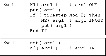
BFG is able to work out whether arg1 is input or output from each model by analysing the definition data for that model. Coupled with the scheduling information, BFG can produce code capable of calculating the source or destination of a field for each timestep at run-time. An example is given in Figure 2 (below) using M1, M2 and M3; it is assumed that the arg1 field is defined in the definition data as an "OUT" argument for M1, an "INOUT" argument for M2, and an "IN" argument for M3:
Figure 2: Example of BFG-generated control code where a field (arg1) can be "put" from different models depending on timestep
In Figure 2, M3 is not guaranteed to run sequentially after both M1 and M2 have completed and therefore the source of arg1 must be computed by get() at run-time. The source put for the M3 get() is determined according to whether the current timestep is even: if the timestep is even, the source (or "target") of the M3 get() is the M1 put(); otherwise the target is the M2 put(). (In the current implementation of BFG2, target computation is performed by BFG functions called put_last() and get_next().) The M3 get() call will then block until the appropriate put() has completed. The fact that M2 is called every other timestep is part of the model definition data - see the <timestep> element of the example definition file.
Note that it is only necessary to calculate the target of arg1 in a concurrent deployment of the model framework - M3 has been deployed in a separate executable from M1 and M2. Where all three models share the same executable and thread, BFG does not need to insert put/get message passing and put/get target computation because the models are guaranteed to run sequentially (see the right-hand column of Table 1 for an example of sequential argpass I/O). It would also be unnecessary to calculate the target for the M3 get() if M2 used the arg1 field solely as an "IN" argument rather than as an "INOUT" argument - in that instance, the only possible source target for arg1 would be the M1 put().
Priming
Priming data describes how a field is initialised at the start of a run. Where a model uses "inplace" I/O for a coupling field, the priming of that field will always take place within the model's source code (i.e. internally), so no priming information is needed in the composition data. Fields that are coupled using "argpass" I/O (entry points) may either be primed internally, or may be primed by the BFG-generated control code, for instance set to a constant or obtained from a namelist file, NetCDF file, or another entry point subroutine (either from the same model or a different one) - priming information is always present for argpass fields.
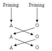
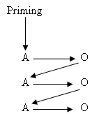
Priming can work differently depending on how a framework is deployed - this can affect the output of experiments conducted with the framework, so needs to be considered carefully by BFG users. Table 2 illustrates the difference in priming between a concurrent model framework using OASIS for I/O ("inplace" I/O using prism_put() and prism_get() to pass fields between models) and a sequential model framework using BFG2.
| OASIS priming (concurrent) | BFG priming (sequential deployment) |
|---|---|
A and O are separate executables for Atmosphere and Ocean models running concurrently. Prism_put() and prism_get() are called with timestamp data that specifies a time frame within which the data is valid. |
A and O are Atmosphere and Ocean models running sequentially. A and O may or may not be separate executables depending on the domain decomposition specified in the BFG deployment data. The models may be using either "inplace" or "argpass" I/O. |
Note that with BFG it is possible to prime and deploy the models in either of the two ways shown in Table 2.
Deployment
BFG deployment data specifies how a model framework will be run - how many executables and MPI processes will be used, what form of I/O will be used for communication between models (e.g. MPI, sequential, OASIS...), and in what sequence model entry point functions will be called. BFG deployment data does not specify where the model framework will be deployed - on what platform or machine it will compile or run. Deployment data determines whether the framework (or parts of it) will run sequentially or concurrently.
Domain decomposition
Domain decomposition describes how the model framework is split into separate executables ("deployment units"), how many threads (sometimes referred to as "execution units", e.g. MPI processes) each deployment unit contains, and which models those threads control. The assignment of models to threads, alongside the information in the schedule, determines the sequence in which the models are run - hence the grouping of models according to thread(s) is referred to as a "sequence unit". Several possible domain decompositions are presented in Figure 3 below for a four-model framework (M1..4):
Figure 3: Three alternative domain decompositions for a four-model framework; DU = Deployment Unit, SU = Sequence Unit, T = number of Threads (Execution Units)
BFG2 is capable of creating control code for all three domain decompositions shown in Figure 3. The left-hand decomposition consists of one deployment unit (executable), with all four models running in sequence and using four separate threads (e.g. MPI processes). The middle decomposition shows the deployment unit split into two sequences (M1->M2 and M3->M4) controlled by separate pairs of threads - in practice allowing M3 and M4 to run before M1 and M2. The right-hand decomposition shows the framework split into two deployment units (executables).
Scheduling
Deployment data includes scheduling information - i.e. the order in which model entry point functions (e.g. initialise and timestep subroutines) run within a framework, assuming a sequential deployment. For instance, the schedule for models M1..3 timestep functions might be as follows:
M1->M2->M3->M1->M2->M3->M1...
The BFG metadata can also be used to describe the structure of more complex control code, e.g. for argument passing models like GENIE. BFG scheduling data is able to represent control code with inner loops or convergence based loops, and model timesteps are specified in the model definition data. (A model may run at a different timestep to the overall framework timestep and the timesteps of other models.) An example of such control code is shown in Figure 4.
!Main model framework timestep loop
For Each timestep
  Call M1( args )

  !Different timestep
  If ( timestep Mod 2 ) Then
    Call M2( args )
  End If

  !Inner loop
  For i = 1 To 5
    Call M3( args )
  End For
End For
Figure 4: A more complex control code with different model timesteps and inner loops
Note that the schedule may not be executed sequentially if the domain decomposition specifies a concurrent deployment for the framework; parts of the schedule are only guaranteed to run sequentially if they belong to the same sequence unit. The schedule is therefore perhaps better described as providing the order for the control code rather than order of execution (which is a function of the schedule, model timestep, and domain decomposition taken together).
Code generation
A fourth metadata file (defined by "coupled.xsd") is used to group the DCD metadata files together, telling BFG where to find the model definition files and the composition and deployment files to use when creating a model framework. BFG then uses an XSLT processor to convert the XML metadata to source code capable of controlling and coupling the model in the way specified by the user DCD metadata.
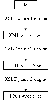
In BFG1, code generation occurred in a single pass, but in BFG2 generation occurs over multiple passes as illustrated in Figure 5; this is due to the added complexity of generating control code for argument-passing models.
Figure 5: BFG2 code generation process
Auto arrays
Where the size of an array isn't known until run-time, BFG2 uses Fortran 90 allocatable arrays, which it ensures are allocated before first use. (Note that GENIE array sizes are fixed at compile-time in the current "native" implementation.)
Unresolved issues
Transformations
BFG2 currently has no set way of carrying out transformations. Three kinds of transformations have been identified:
- Unit transformations - e.g. from Celsius to Kelvin;
- Spatial transformations - projecting field values from one grid onto another grid, typically using a form of interpolation as carried out by OASIS;
- Temporal transformations - the "rate matching" necessary when models are coupled at a different rate to their timestep, or where timesteps differ between models. For instance an atmosphere model might have a timestep of 30 minutes, and an ocean model a timestep of 2 hours, with coupling occurring every 24 hours.
When using BFG with OASIS, these transformations are carried out by OASIS itself. However, the BFG developers would like to support transformations independently of OASIS. For instance, it may be desirable for BFG to generate frameworks using MPI or sequential argument passing, and using the Spherical Coordinate Remapping and Interpolation Package (SCRIP) library for grid transformations. (OASIS4 uses SCRIP "under the hood"; more information on SCRIP here: http://climate.lanl.gov/Software/SCRIP/.)
GENIE framework generation
The BFG developers are currently working on an implementation of the GENIE framework that does not exchange geographical (gridded) data between models, and therefore doesn't need OASIS or SCRIP for spatial transformations. The GENIE framework with non-gridded coupling is a step towards generating an instance of the GENIE framework that does require gridded coupling, and carries out that coupling using OASIS. BFG will require additional model definition data to do this - a gridspec that describes a model's grid, and can be used to generate appropriate PSMILe grid initialisation code for coupling with OASIS. The temporal and unit transformations that are carried out in the non-gridded BFG-GENIE framework are currently being included as models in the own right. The BFG-generated GENIE framework therefore consists of two types of model: "scientific" models, and "transform" models. This approach may or may not be used in future - another approach would be to include transforms in the BFG metadata.
BFG and FLUME
The Met Office is currently working on a new system architecture for the Unified Model -- the Flexible Unified Model Environment (FLUME). FLUME uses a customised version of BFG: as well as making use of the "Define, Compose, Deploy" methodology, the Met Office framework generator has an additional "Configure" phase, which allows component model definitions to be customised for a specific experient. For instance, the user may select a subset of the initialisation and timestep subroutines described in the Definition data (where this makes sense), causing a component model to run with or without certain features or behaviour. This is a useful step particularly for large climate models like the UM that can be run in many different ways, and to which new features are regularly being added.


